








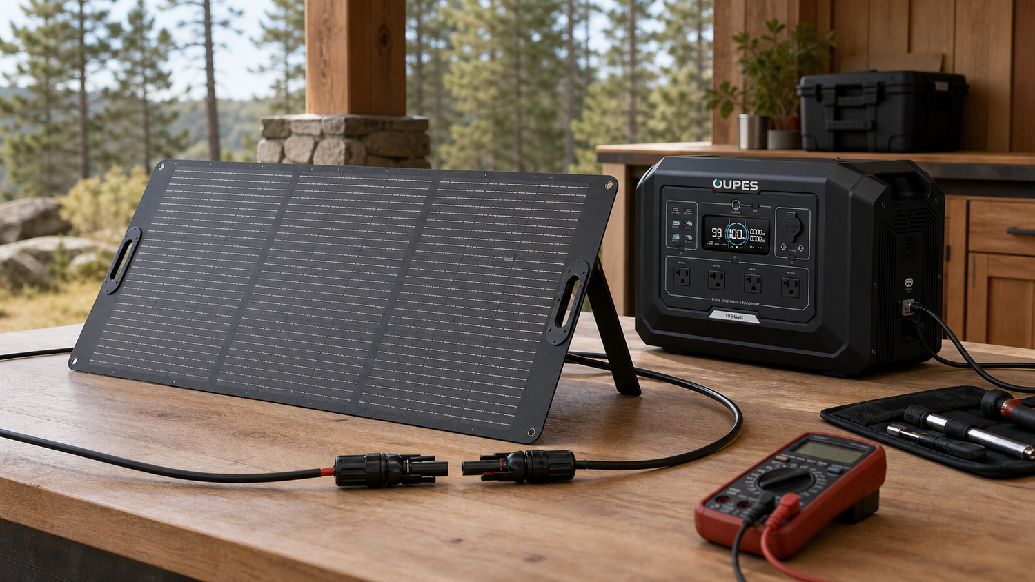
MC4-style connectors are common on portable and fixed solar panels, but a connector that physically fits does not prove electrical compatibility. You must verify polarity, open-circuit voltage, operating voltage, short-circuit current, cable gauge and the power station's entire solar input window.
This guide gives a practical way to turn the main keyword solar panel electrical connectors into a real load plan. The examples are planning estimates rather than product guarantees. Actual results change with device cycling, startup demand, temperature, battery condition, conversion losses, cable length, solar weather and the way equipment is used.
Quick Answer
MC4-style connectors are common on portable and fixed solar panels, but a connector that physically fits does not prove electrical compatibility. You must verify polarity, open-circuit voltage, operating voltage, short-circuit current, cable gauge and the power station's entire solar input window.
The safest buying sequence is to confirm the load, calculate required energy, check continuous and startup power, and only then select a battery and charging method. A high inverter rating cannot compensate for insufficient watt-hours, and a large battery cannot run an appliance whose voltage or startup demand is incompatible.
Understand the Ratings Before Buying
Record panel Voc, Vmp, Isc and Imp at the expected coldest conditions. Record the station's maximum input voltage, MPPT range, current limit and connector. Compare the complete series or parallel array, not a single panel.
Watts describe power at a moment. Watt-hours describe energy used over time. Amps describe current, while voltage is the electrical pressure that drives it. For a simple DC estimate, watts equal volts multiplied by amps. AC appliances may also involve power factor, so the label or direct measurement is preferable to an assumed calculation.
For motors, compressors and pumps, look for startup or locked-rotor demand as well as ordinary running power. For batteries, compare the published capacity, output waveform, port-specific limits, operating temperature and cycle-life definition. Do not assume that every socket can provide its printed maximum simultaneously; shared system limits usually apply.
Typical Power Ranges
The ranges below are orientation values, not substitutes for the actual equipment label. Two devices with the same general description can have very different efficiency, control logic and startup behaviour.
| Device or System | Planning Range | Important Qualification |
|---|---|---|
| MC4 pair | Locking positive/negative DC connection | Polarity must be confirmed |
| DC barrel plug | Small portable inputs | Many sizes look similar |
| Anderson-style connector | Higher-current modular DC connection | Housing and pin orientation vary |
| Proprietary adapter | Matches a brand input | Check current rating and official compatibility |
Calculate Energy and Runtime
Use three simple formulas:
- Energy used (Wh) = average watts x operating hours.
- Required rated battery (Wh) = load energy / assumed usable-system factor.
- Estimated runtime (hours) = rated Wh x usable-system factor / average load watts.
The examples use an 85% usable-system factor to represent inverter and conversion losses plus a small operating margin. This is not a guaranteed efficiency figure. Heavy loads, cold temperatures, aging, power factor and battery protection limits may reduce the result.
| Example Load | Calculated Energy | Planning Battery at 85% |
|---|---|---|
| Two 24.6V Voc panels in series | 49.2V Voc | Current stays near one panel |
| Two 11.7A Imp panels in parallel | About 23.4A Imp | Voltage stays near one panel |
| 240W at 20.5V Vmp | About 11.7A | Matches published OUPES panel Imp |
| 100W at 20.5V Vmp | About 4.88A | Matches published OUPES panel Imp |
Measure cycling equipment over a representative period instead of multiplying its running watts by 24 hours. Refrigerators, pumps, air conditioners and many chargers switch on and off. Conversely, do not ignore short high-power events: they may determine the inverter size even when their total energy is small.
Step-by-Step Sizing Method
- List essential loads. Separate safety, medical, communications and property-protection needs from optional comfort devices.
- Record real ratings. Use nameplates, manuals, EnerGuide data or a suitable meter. Include every adapter and accessory.
- Calculate daily watt-hours. For cycling devices, use measured energy or a realistic duty cycle.
- Check simultaneous watts. Add only the devices that may operate at the same time, then include practical headroom.
- Check startup and voltage. Confirm the largest realistic motor event and every 120V, 240V or regulated DC requirement.
- Plan recharge. Decide how much energy must be restored by AC, vehicle or solar input before the next use period.
- Add uncertainty. Weather, cold, device aging, extra users and delayed travel all justify reserve capacity.
Planning by Scenario
| Scenario | Practical Starting Strategy | Constraint to Verify |
|---|---|---|
| One portable panel | Use the supplied compatible lead | Confirm polarity before first use |
| Series array | Raises voltage for lower cable current | Cold Voc must stay below maximum |
| Parallel array | Raises current and shade tolerance | Input and connector current limits apply |
| Mixed panels | Avoid unless electrical characteristics are properly engineered | Mismatch can reduce output or create risk |
A planning table is useful because it exposes trade-offs. The lightest system is easier to move but offers less resilience. A larger system extends runtime but costs more, weighs more and may need a stronger solar array or AC circuit to recharge within the available window.
OUPES Product Options
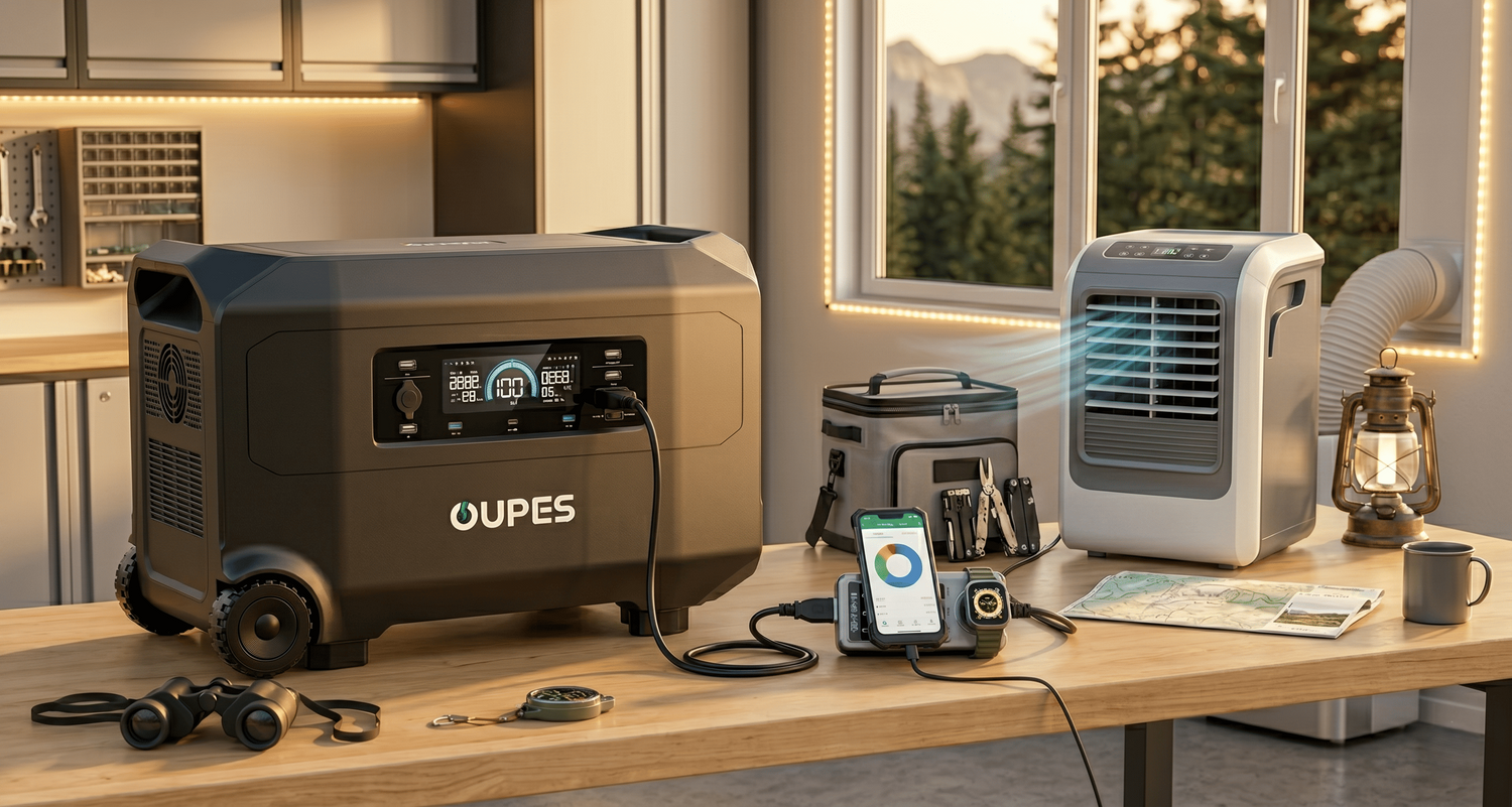
OUPES models should be recommended only when their verified output, capacity, ports and charging limits fit the load plan. The following comparison uses specifications published on the Canadian product pages. Availability and bundle pricing can change, so confirm the live page before publication.
| OUPES Model | Capacity | Rated AC Output | Published Solar Input | Best-Fit Role and Limitation |
|---|---|---|---|---|
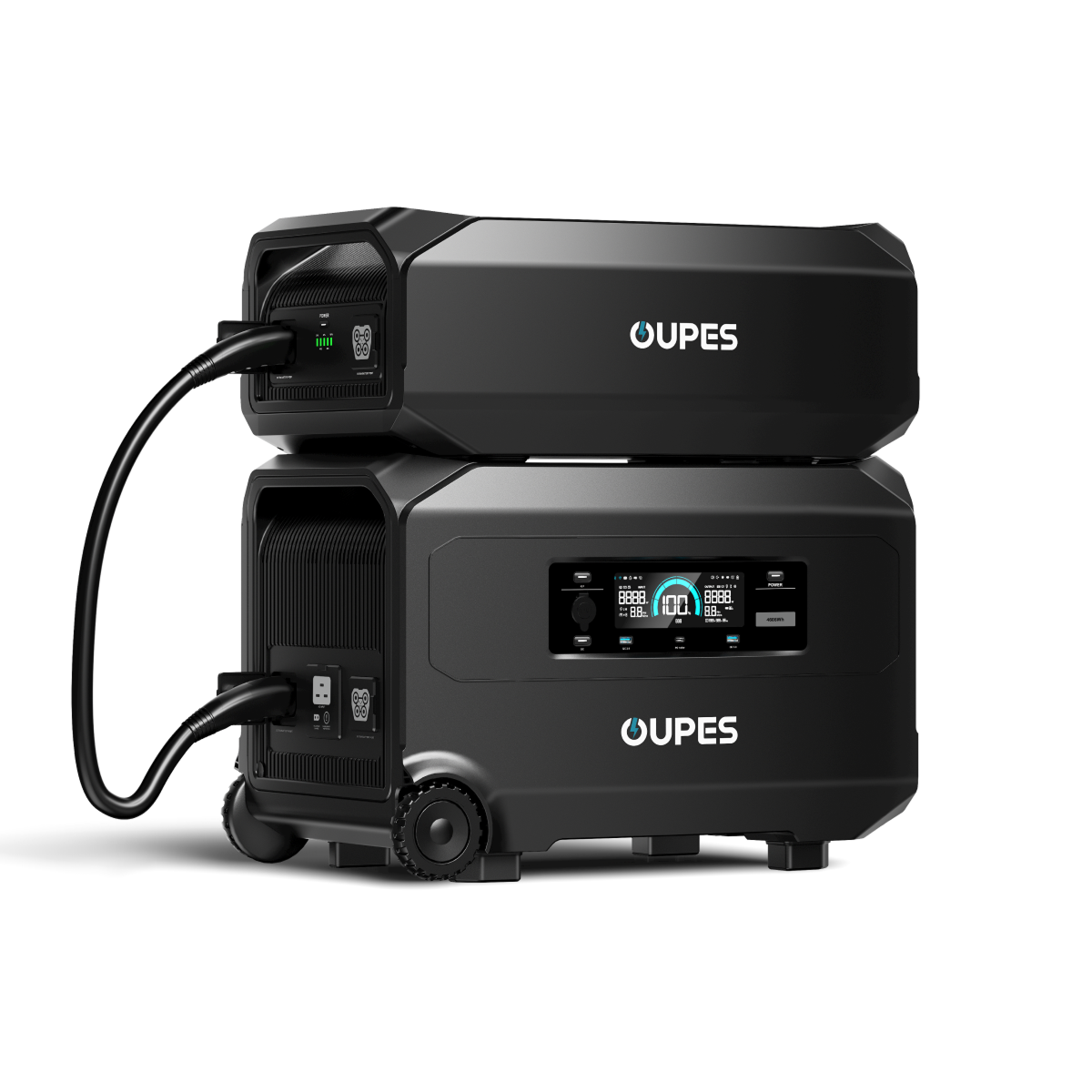
| OUPES Exodus 1200 | 992Wh | 1,200W | 240W max | Light camping, communications, CPAP planning and managed essentials. Best starting point when the solar panel electrical connectors plan is efficient and tightly managed. |
| OUPES Mega 1 | 1,024Wh | 2,000W | 1,200W max | Higher-watt appliances, short home backup and mixed mobile loads. Useful when the plan includes brief high-watt loads or requires more output headroom. |
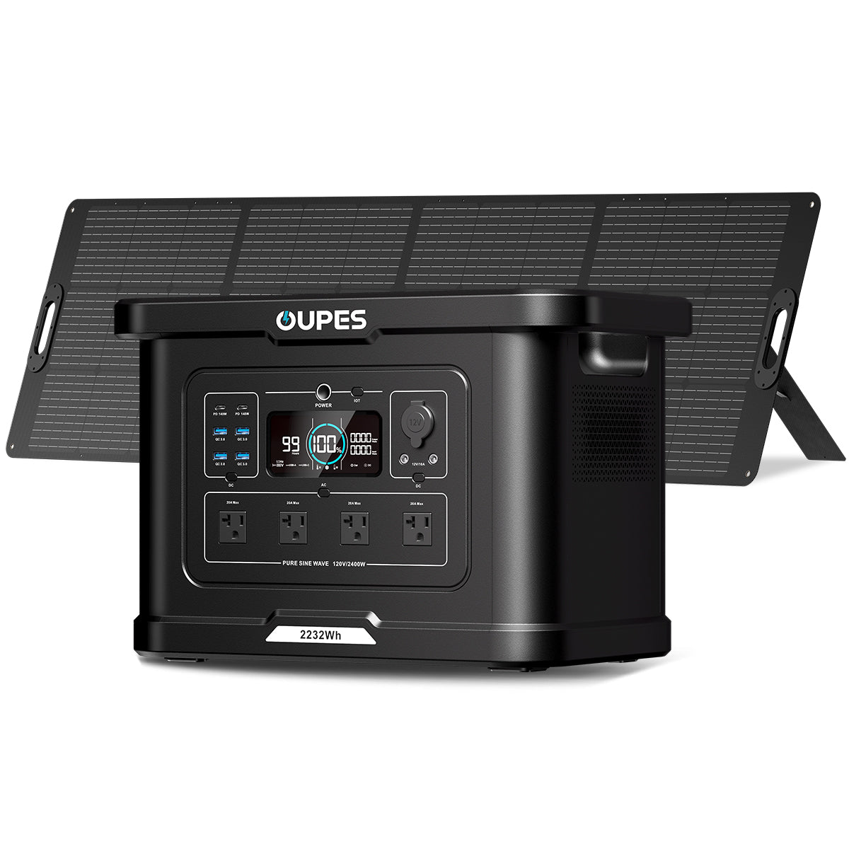
| OUPES Exodus 2400 | 2,232Wh | 2,400W | 800W max | Longer runtime and demanding 120V loads; currently shown as sold out on the CA site. Adds substantially more stored energy for longer sessions; confirm current availability. |
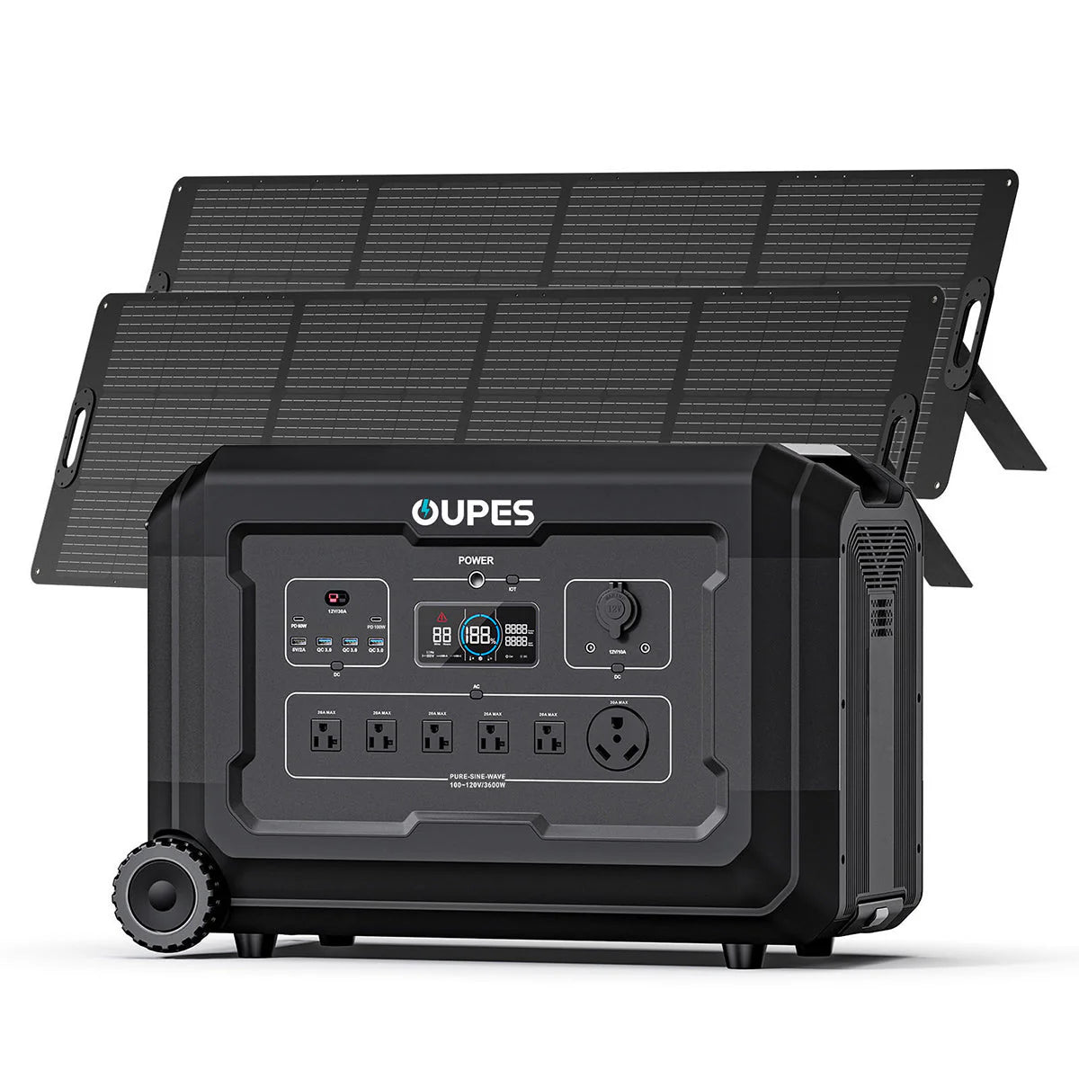
| OUPES Mega 3 | 3,072Wh | 3,600W | 2,100W max | Home backup, RV use and larger simultaneous load plans. Best suited to broader home, RV or multi-load plans that justify the extra capacity and weight. |
The OUPES Exodus 1200 is the lighter 992Wh option, while the OUPES Mega 1 combines 1,024Wh with 2,000W output. The OUPES Exodus 2400 provides 2,232Wh and 2,400W but is currently marked sold out on the Canadian site. The OUPES Mega 3 offers 3,072Wh, 3,600W output and expansion for larger plans. Choose from the measured requirement rather than assuming the largest model is automatically best.
You can also review the Canadian portable power station collection. Use the commercial category link once, then let the product specifications and the user's scenario drive the recommendation.
Solar and Recharging
Solar charging should be planned from daily energy. A rough estimate is panel watts x equivalent full-sun hours x system factor. A 240W panel with four equivalent full-sun hours and a 70% planning factor would provide about 672Wh in that example day. Clouds, shade, snow, orientation, temperature, cable loss and the station's input limit can all reduce the result.
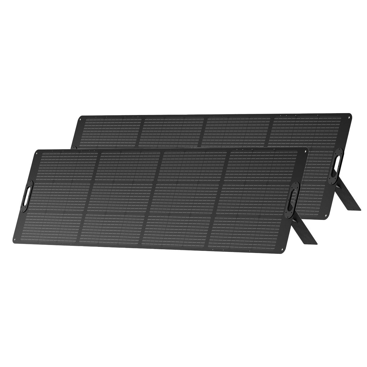
The OUPES 100W and 240W panels list monocrystalline cells, MC4 connectors and at least 23% cell efficiency. The 100W panel lists 24.4V open-circuit voltage and 4.88A operating current; the 240W model lists 24.6V open-circuit voltage and 11.7A operating current. Before combining panels, calculate total voltage and current and compare them with the selected station's entire MPPT window.
For a combined battery-and-panel package, review the Canadian solar generator collection. Nameplate solar wattage is not guaranteed field output, so critical plans need reserve energy or another compatible charging route.
Safety and Canadian Conditions
DC arcs can persist. Disconnect or cover panels before changing connections, use the correct release tool, never separate connectors under load unless rated for it and replace damaged seals or cables.
Canadian conditions introduce real planning limits: winter days are short, snow and shade affect panels, cold can limit charging, and summer heat can increase cooling or refrigeration demand. Use equipment only within its published operating and storage temperatures. Keep vents open, inspect cords and connectors, and stop using anything that is damaged, unusually hot or wet.
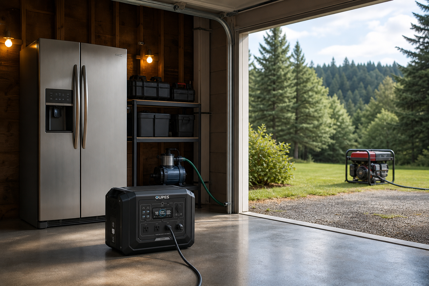
Fuel generators are a different category from battery systems. They create carbon monoxide and must remain outdoors at the distance and orientation required by current safety guidance. A battery unit avoids combustion exhaust at the point of use, but it still requires dry conditions, ventilation and safe wiring.
Common Mistakes to Avoid
- Choosing from one headline watt number without checking watt-hours, surge, voltage and ports.
- Using advertised appliance output instead of electrical input.
- Assuming rated battery energy is fully available as AC energy.
- Using the best solar day as the normal or worst-case charging day.
- Ignoring simultaneous loads, compressor startup or pump cycling.
- Using unverified adapters, reversed DC polarity or undersized extension cords.
- Connecting backup power to a building through an improvised backfeed cord.
- Publishing a runtime estimate without stating its efficiency, duty-cycle and weather assumptions.
Final Verdict
MC4-style connectors are common on portable and fixed solar panels, but a connector that physically fits does not prove electrical compatibility. You must verify polarity, open-circuit voltage, operating voltage, short-circuit current, cable gauge and the power station's entire solar input window.
For a reliable decision, measure first and buy second. Match inverter power to the worst realistic simultaneous and startup load; match battery watt-hours to the target runtime; and match solar or AC input to the energy that must be restored. Leave reserve for the conditions that a simple calculator cannot predict.
Frequently Asked Questions
Are all MC4 connectors compatible?
Not necessarily. Similar-looking connectors from different manufacturers may not be certified for mating, and polarity still needs verification.
Can I reverse solar polarity?
No. Reversed polarity can damage equipment; confirm with labels, approved adapters and a meter when appropriate.
What changes in series wiring?
Voltages add while current remains approximately that of one string.
What changes in parallel wiring?
Currents add while voltage stays approximately that of one panel.
Can I exceed the station's solar watts?
Never exceed voltage or current limits. Some systems allow array nameplate power above the accepted wattage, but only when the manufacturer explicitly permits it.
What connectors do OUPES panels use?
The CA-site 100W and 240W panels list MC4 connectors; use the appropriate OUPES input cable for the selected station.
Sources

Leave a comment
This site is protected by hCaptcha and the hCaptcha Privacy Policy and Terms of Service apply.